
Goldorak 2016 post-mortem
Until two years ago, the robots we developed for Eurobot, were centralized systems. An FPGA board powered the robot: reading sensors, controlling actuators, and running all the control loops. An auxiliary computer provided access to higher level features such as computer vision, and it sometimes was used to run the strategy.
However, due to an increasing number of actuators on the main robot: Debra (a robot we started developing in 2011 as a reusable platform with a differential base and two SCARA arms), we decided to shift to a distributed architecture.
Thus, the FPGA was replaced by several motor boards, a single master board, and the embedded computer remained.
- The motor boards are little boards we designed in 2014-2015 that use a STM32F3 microcontroller to control a single motor in torque, velocity, and position. They were connected through a CAN bus to the master board.
- The master board is an STM32F4 board from Olimex (Olimex E407) connected to CAN, and to the computer via Ethernet.
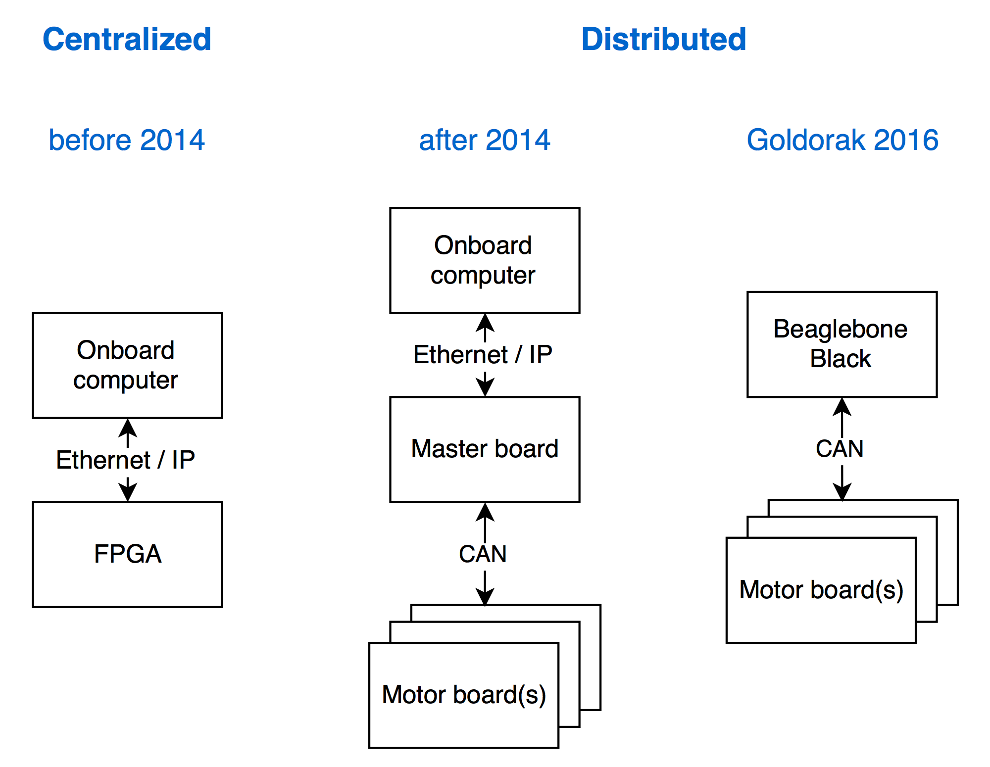
The motor boards1 were controlled over the CAN bus, then an IP link with a custom RPC protocol bridged the CAN bus with the computer.
As with all projects, we had delays, so in 2015 we weren’t able to homologate at the SwissEurobot competition, although we managed to win a Jury award for best design.
Last October, @antoinealb and I, decided after a trip to ROSCon 2015 in Hamburg2, we want to experiment with CAN directly on a computer, and leverage all the tools and libraries provided by ROS and SocketCAN in order to build the small robot for Eurobot. It was dubbed project Goldorak, and the name stuck, so the robot was named Goldorak3.
This post goes through our journey, the limitations we hit when using ROS for Eurobot on a microcomputer (the BeagleBone Black), and the lessons learned from it.
ROS meets UAVCAN
CAN on Linux
The choice of an embedded computer was pretty straightforward. I had previously worked with the BeagleBone Black and grew acquainted with it. It provides CAN and Ethernet off-the-shelf. So we chose to use the BeagleBone Black as our embedded computer.
At first, we did the setup by hand, but later on we automated it using SaltStack4. Installing and setting up SocketCAN was quite easy5.
Bridging UAVCAN with ROS
In order to use the motor boards we designed the previous year, our BeagleBone Black had to speak UAVCAN. We needed to send PID parameters and setpoints, and to also receive feedback if needed.
First, a ROS-UAVCAN bridge was the first node to be written. We wrote it in C++ since UAVCAN’s Python implementation was not as mature back in October. The process was quite straightforward, but boring and repetitive: for each message structure supported by the motor board, there are a ROS publisher and a UAVCAN subscriber, or vice versa.
Each motor board had a name and node ID to identify it.
The CAN messages were relayed onto ROS topics divided between setpoint and feedback, and organized by namespace: each node name defined an associated namespace.
Take the right_wheel node for example, the associated list of topics looks like this.
/right_wheel/feedback/encoder
/right_wheel/feedback/index
/right_wheel/feedback/position
/right_wheel/feedback/torque
/right_wheel/feedback/velocity
/right_wheel/feedback/voltage
/right_wheel/feedback_pid/current
/right_wheel/feedback_pid/position
/right_wheel/feedback_pid/velocity
/right_wheel/setpoint
We can control the right wheel of the robot by sending a message over the right_wheel/setpoint topic and receive feedback from it through several topics under the namespace right_wheel/feedback.
One especially useful feedback is /right_wheel/feedback/encoder providing external incremental encoder values used for positioning.
The right_wheel/feedback_pid namespace was dedicated to feedback for PID tuning which included setpoints along with measurements of the same quantity.
PID tuning over CAN
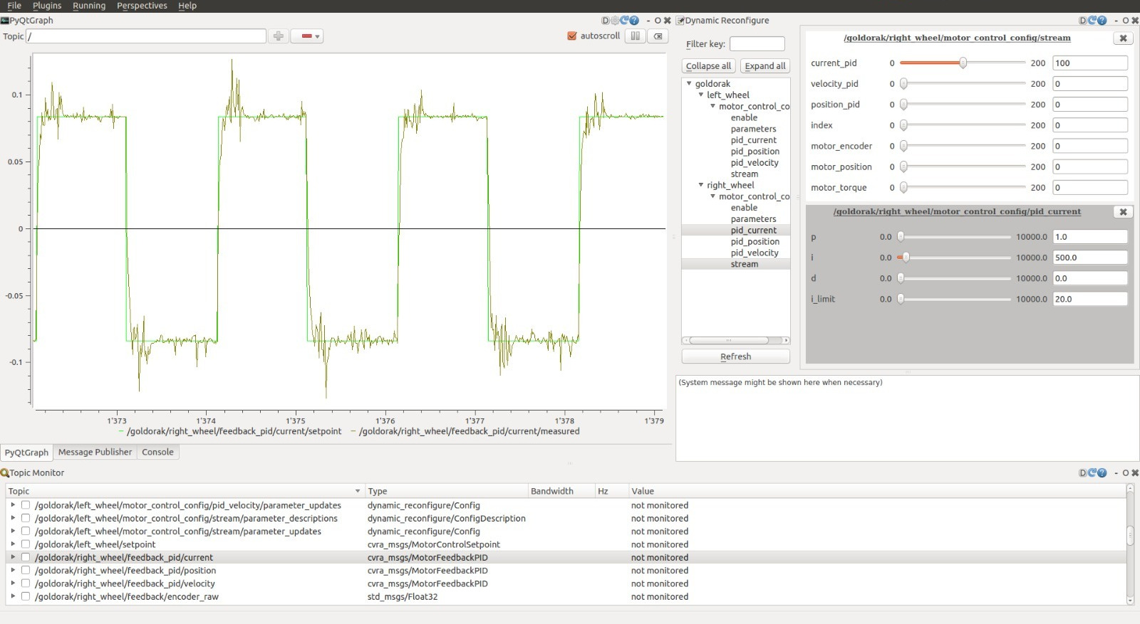
Using RQT for plotting and using dynamic reconfigure to send PID parameters to the motor boards, we setup a nice interface to tune the PIDs of the motor board:
- Setpoints and measured outputs are plotted in top left (PyQtGraph plot)
- PID parameters are tuned through the widget in top right (dynamic reconfigure)
- Topics are monitored and selected for plotting, from the bottom widget (topic monitor)
Making Goldorak a ROS enabled robot
Once our differential base’s motors were controllable through ROS nodes, and our PIDs were tuned, we were ready to build an abstraction of the wheelbase to be used for robot motion.
In order to control a robot the ROS way, you need to expose a node that subscribes to the /cmd_vel topic of type geometry_msgs/Twist.
This is a message describing a desired velocity in linear x,y,z and rotational x,y,z axis (roll, pitch, yaw) to be performed by the robot.
geometry_msgs/Vector3 linear
  float64 x
  float64 y
  float64 z
geometry_msgs/Vector3 angular
  float64 x
  float64 y
  float64 z
For a robot with differential base, this is quite easy, since you can only apply a combination of linear x and angular z (yaw) velocity. The equations are also straightforward:
velocity_right = (velocity_forward + (track / 2.f) * velocity_yaw) / radius_right;
velocity_left = (velocity_forward - (track / 2.f) * velocity_yaw) / radius_left;
Where track is the distance between the two differential driving wheels.
Moving the robot is nice, but the robot also needs to know where it is. For that, we use incremental encoders placed on additional external wheels, that we call odometers (i.e. not the motor driving wheels). Odometry equations are simple for a differential base.
Our system, however, is a bit more complex due to its distributed architecture.
Indeed, the two odometers are wired and handled by two separate microcontrollers so there is no synchronisation between their samples.
A solution to this problem is to predict the encoder value of the wheel with the oldest sample at the time of odometry computation.
This asynchronous odometry was implemented last year, so it was only a matter of wrapping it in a node and subscribing to the right topics to get encoder values.
The estimated robot pose is published to the /odom topic which is a nav_msgs/Odometry type of message.
std_msgs/Header header
  uint32 seq
  time stamp
  string frame_id
string child_frame_id
geometry_msgs/PoseWithCovariance pose
  geometry_msgs/Pose pose
    geometry_msgs/Point position
      float64 x
      float64 y
      float64 z
    geometry_msgs/Quaternion orientation
      float64 x
      float64 y
      float64 z
      float64 w
  float64[36] covariance
geometry_msgs/TwistWithCovariance twist
  geometry_msgs/Twist twist
    geometry_msgs/Vector3 linear
      float64 x
      float64 y
      float64 z
    geometry_msgs/Vector3 angular
      float64 x
      float64 y
      float64 z
  float64[36] covariance
Now our robot is compatible with the ROS navigation stack. Yay!
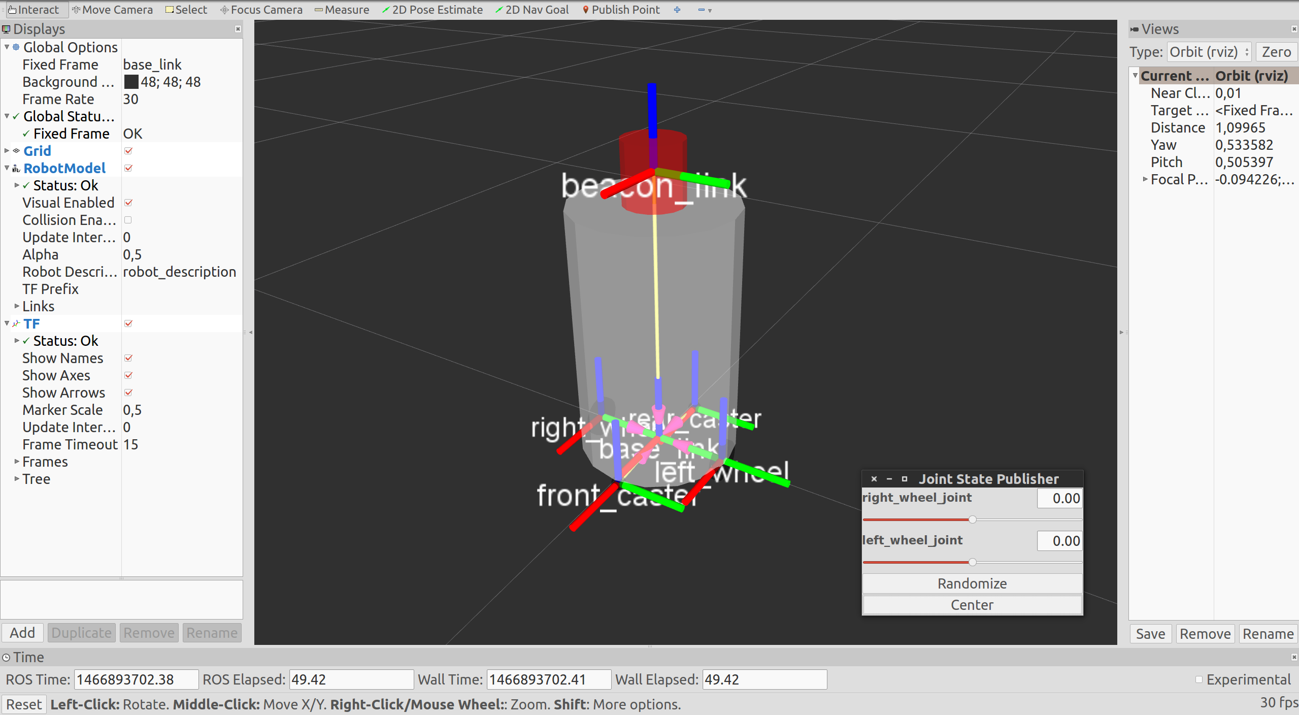
But that was not enough for us, we also wanted to visualise our robot in Rviz… in 3D!
In order to achieve that you need a joint state publishing node to broadcast the state of the wheel joints, this will alow you to see the wheels rotating in Rviz.
Then running the robot_state_publisher node we would get the TF of all the links specified in our URDF robot description.
This was a simple model of the robot with two wheels, two caster links, the body and a beacon link6.
Using ROS navigation stack for Eurobot
So now we can control our robot, know where it is and visualise it in real time. Time to make it navigate!
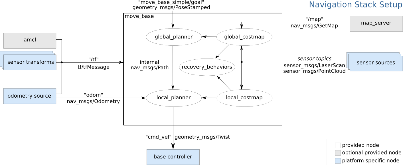
The ROS navigation stack is a set of motion planners based on a discrete costmap approach. It consists of a global planner and a local planner.
- The global planner solves the problem of going from point A to point B in spatial coordinates (x, y, z) given a discrete map with obstacles (occupancy grid). This problem is typically solved using A*, Djikstra and/or potential field algorithms.
- The local planner will locally compute a feasible trajectory on the global plan (result of the global planner) taking into account desired arrival orientation and kinematic constraints (holonomic or not, fully actuated or underactuated). Popular implementations of local planners include the simple trajectory rollout, the Dynamic Window Approach, the Elastic Band Approach to cite a few.
The navigation stack also supports inputs from a laser scanner, but we didn’t use it on Goldorak since we only had one that was already used on Debra.
Setting up the navigation stack is not black magic, a nice guide is provided in the tutorials and if you follow it you’ll be OK. Tuning the navigation stack, now that was another story. I was able to tune the parameters when running the navigation nodes on my laptop using DWA as local planner. The result was pretty cool.
But as soon as it had to run on the BeagleBone Black, we would hit the computational limits of the platform, so we had to tune the parameters sub-optimally to run on it. We switched to trajectory rollout for local planning, and increased the goal tolerances while decreasing update rates of costmaps and control.
The result was OK, although not sufficient for the tasks at hand. We only realized these limitations a few weeks before the contest when we started testing the fishing module for the competition. By then, it was too late to change much in our approach to the problem. Retrospectively, a possible solution would have been to use the spare Intel NUC of Debra and connect it to the BeagleBone Black, then have it run all nodes except the UAVCAN bridge which would run on the BeagleBone Black.
Computers are all fun and games until they are not
Saving CPU resources on the BeagleBone Black
Now that our navigation was consuming up to 70% of CPU time on the BeagleBone Black, we needed to think carefully about how we used our resources. We switched time critical nodes into nodelets to save some CPU time. Nodelets are a way of writing a node such that it can benefit from zero-copy publish/subscribe and free us from some overhead of processes while maintaining the introspective capabilities of ROS. One major setback was that we weren’t able to wrap the UAVCAN bridge into a single thread or a nodelet.
We also played with nice, a Unix tool that allows you to set the priority of a process. This way we were able to give priority to control nodes.
BeagleBone Black’s limitations as ROS platform
Along the journey, as we had more and more nodes to build for our robot to run, the build time increased from a few seconds to ~20 seconds. This effect was more dramatic on the BeagleBone Black, we went from a few tens of seconds to a full record of 20 minutes of painful compilation time. It felt like writing software in the 1960 where you had to wait until next day after the code you wrote was punched into cards and ran by a computer operator.
A logical reaction of ours was to try crosscompiling for the BeagleBone Black on our machines. We crosscompile everyday for ARM cortex-M microcontrollers that run our motor boards and such. So crosscompiling must be easy, right? Well… turns out it’s not. After a few minutes of Google search, you realize that no one ever crosscompiles ROS nodes, and you wonder why. So you try to make it crosscompile on your own. You sacrifice a few goats7, and you learn more than you would like to know about CMake, and you managed to compile, but then crosscompilation crushes you because you will NEVER link against ROS libraries. You heretic, how dare you think about crosscompilation8.
So if you were thinking about crosscompiling your ROS nodes, then think about something else to do with your life, maybe become a farmer and grow some corn: agriculture makes more sense than computer science, at least it’s governed by laws of physics.
2016 Competition summary
The swiss contest took place on May 2016. With Goldorak, we intended to perform several actions:
- Shell collection using grippers (2 points per shell)
- Door closing (10 points per door), this task was left to the bigger robot, Debra
- Fish collection in the water (10 points per fish in net and 5 if in the robot) using a dedicated module (2-axis cartesian with impeller and magnets)
- Beach umbrella deployment using a pneumatic tank (20 points) on which Mathieu wrote a great article
With all the software, mechanical and integration hassles encountered, we only managed to perform the last two actions.
The umbrella deployment worked flawlessly. The electrovalve commanding the pneumatic release was controlled by a motor board acting as on/off switch and DC-DC regulator. The umbrella was successfully deployed in all our 7 matches.
The fishing sequence had high requirements on the position of the robot relative to the border. The left side of the robot had to be less than 2cm away from the border to allow the impeller to deploy correctly in water and attract the fish to be caught using magnets.
In the end, fishing sequence had to be hacked around due to the poor performance of the navigation on our CPU-bound platform. We managed to collect between 0 and 2 fish per match for a total of 9 fish in 7 matches, and we successfully deposited 7 fish in the net (1.14 fish per match in average if counting fish in robot as 0.5 fish).
An unexpected problem was getting stuck by a shell and thus getting lost. Another common problem was the navigation oscillating around its goal at the 2nd or 3rd fishing sequence, after which the robot would freeze until the end.
In average, the small robot scored 31.4 points per match, well below the maximum 90 points envisioned at the design phase (70 if we don’t count the door closing action).
Closing remarks
To finish this long article, here is a list of things to remember:
- ROS communication stack is stable and very nice to have, it makes node debugging easier and feature implementation faster.
- ROS navigation stack is fun and very useful for large scale robots navigating among humans but for Eurobot it’s overkill and requires a very powerful onboard computer to run properly. The navigation stack is well suited for probabilistic navigation and avoiding unpredictible obstacles, however Eurobot requires more precise and repeatable positioning.
- ROS visualisation tools are very useful but tend to crash sometimes which is kind of frustrating (but it doesn’t matter since processes are decoupled).
- Smach is a cool library for writing a state machine for your strategy but its viewer crashes all the time.
- There is a nice framework to write tests with ROS nodes but the feedback loop is too long to use effectively for Test Driver Development.
- We didn’t manage to cross-compile ROS packages to ARM which slowed down our development as we approached the contest and the changes were only testable on the real hardware.
- We lacked thorough testing due to delays in manufacturing and assembly of the robot and very long feedback loops between two tests on the robot.
- Having a computer on board your robot for Eurobot is nice for CPU hungry computation, but don’t use a microcomputer such as the BeagleBone Black or the Raspberry Pi. These boards are nice for tinkering but they tend to have long boot times and slow CPUs. They can’t be used as replacement for a more conventional computer in all applications. Also note that it’s not as simple to use IO as it is on a microcontroller9.
- Keep your stack as simple as your application requires.
- We are going to use a microcontroller board as master on our robots. That doesn’t mean we won’t use an onboard computer, just that it will be a slave and won’t be a critical component of the robot.
Footnotes and links
-
Setup of the BeagleBone Black used on Goldorak, our small robot. ↩
-
My BeagleBone Black setup for embedded and robotics development. ↩
-
The beacon system we used this year consisted of an optical obstacle detection based on an emitter and receiver on our robots and a reflector on the opponent’s robots. ↩
-
No goats were harmed in the making of this article. ↩
-
In order to use IOs on Linux, you need to setup the device tree overlays and use sudo. You can use sysfs to run without sudo, but that can’t be applied to all peripherals. ↩