Eurobot 2015: RoboMovies
Becoming a movie star isn’t easy: acting isn’t enough! The robots will experience it this year, and will have to show us their multiple talents in an extraordinary shoot.
They have several tasks to do:
- The spotlight: The robots will have to install them as high as possible in order to illuminate the movie actors.
- The clapperboard: The robots will have to close their clapperboards.
- The popcorn: The robots will have to gather popcorn and put it in their popcorn basket.
- The red carpet: The robots will have to roll out the carpet on the steps in order to welcome the artists.
- Climbing the red carpet steps: The robots will have to go the top of the steps before the end of the match.
Our robots
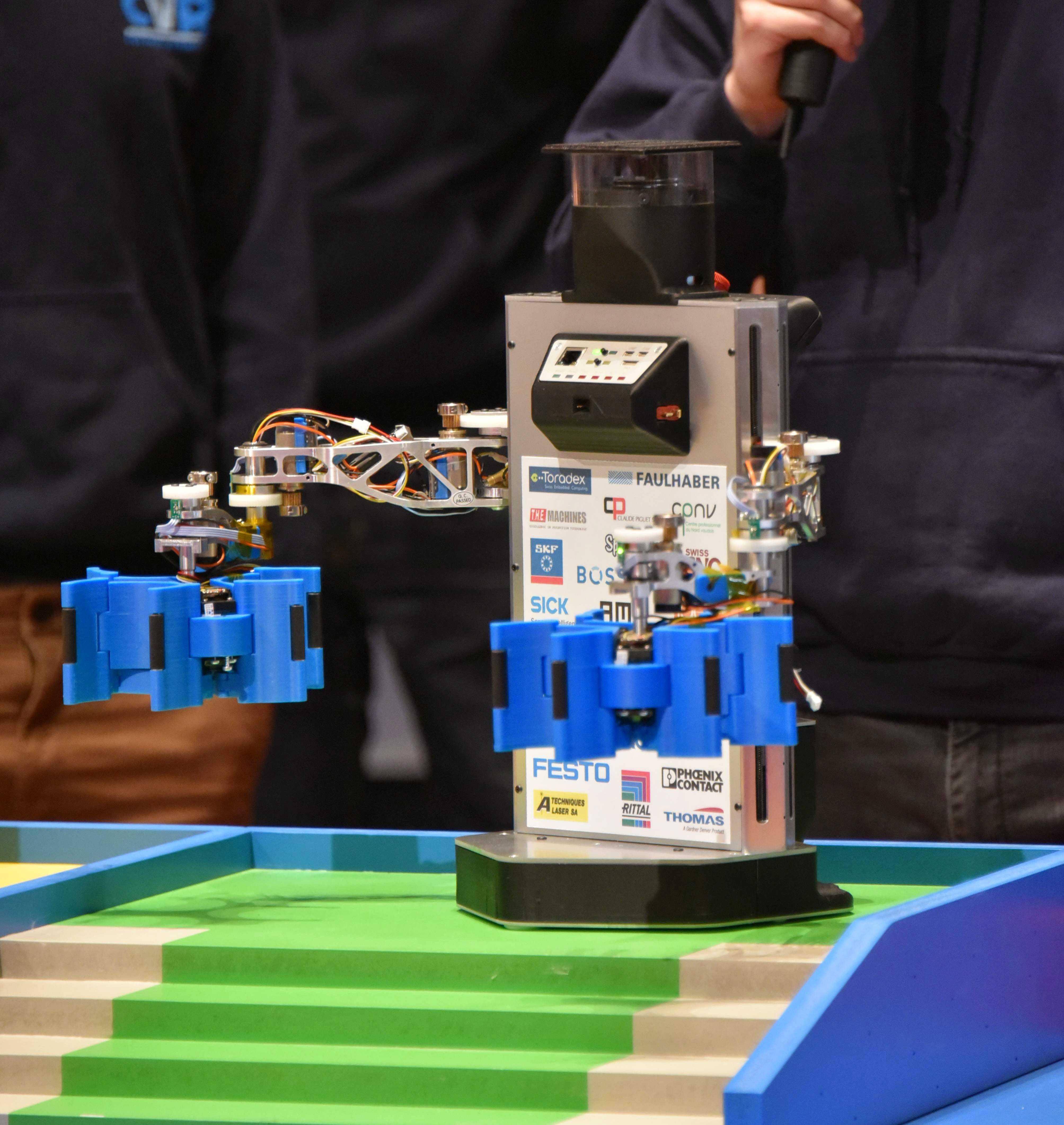
Debra 5
Debra is our biggest robot. It has two arms, as each year, allowing it to grab and stacks the spotlights, as well as close the clapperboards.
Debra also has two cameras to see around it, which sadly wasn't implemented.
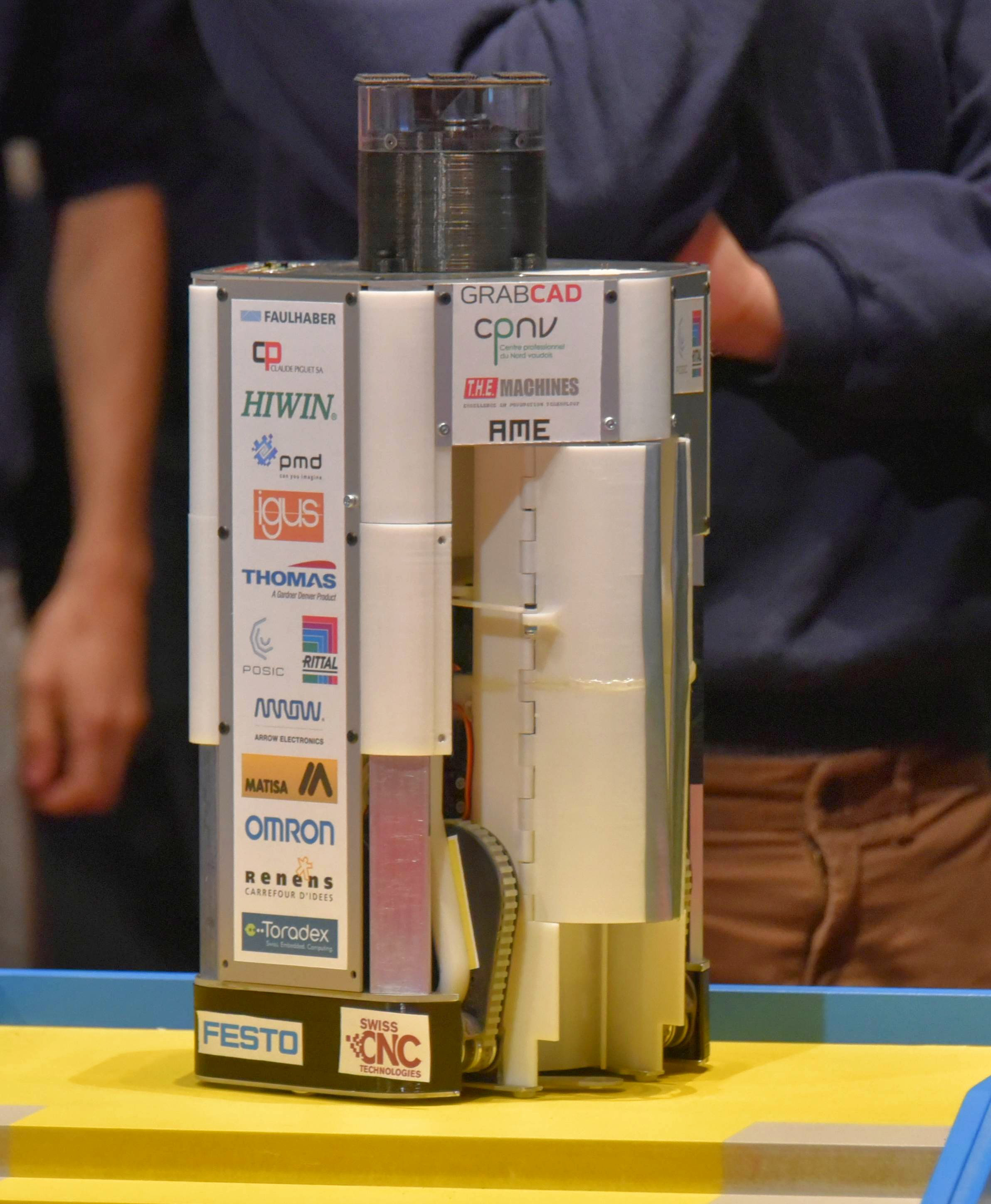
Caprica
Caprica is our smaller robot, named after the Battlestar Galactica TV series. Its also capable of stacking the spotlights but it was mostly designed to climb the stairs using caterpillars. Caprica also has a simple system to drop the carpets once it is on top of the stairs.
Technologies
In 2014 we reached the maximum number of motors that our FPGA-based design could handle. We also wanted to get rid of Altera’s tools, which were too complex and too constraining for our use.
We decided to try ST’s STM32 ARM based microcontrollers since some of our team members had a lot of experience with those. A big part of the summer was spent hacking on those to make something work and at the release of the rules we knew we would switch to those.
We wanted to drive at least 14 motors with quadrature encoders and the more the better. Since it was obvious that no microcontroller could handle it we decided to switch to a new paradigm: each motor would have its own control board which would be connected to a network. This design would allow us to horizontaly scale the number of motors to any number we wanted, provided we respected the network’s maximum bandwidth. Sadly it also meant that the board should be small: we had a limit of 25 by 35mm.
We studied a bit the various field busses that we could use:
- EtherCAT is a big technology lock-in, takes a lot of PCB room and is expensive. On the other hand it brings excellent realtime performance has a huge bandwidth and good vendor support.
- Ethernet has excellent vendor support, is compatible with lots of different platforms and offers good performance. It is only available on high end microcontrollers which did not fit in the maximum size limit for the board.
- CAN is cheap and compact, offers good enough performance and has built in bus arbitration. It uses few external components and wires and is well documented. This is the one we chose.
- We also took a look at other communication busses such as RS-485 and I2C but they were quickly put away due to critical limitations (bandwidth, interference sensitivity, etc.).
The embedded PC delegates realtime tasks to a master board which serves as a gateway between the CAN bus and a standard Ethernet/IP communication. This board is also based on an ARM microcontroller.
CAN bus
Running a complex application such as a robot requires complex network functionalities such as adressing, packet fragmentation and service requests (client server architecture). While CAN provides some networking primitives such as message IDs or bus arbitration, it lacks those high levels concepts. Typically this is solved by adding a protocol between the CAN network and the application, such as CANopen, CANaerospace or DeviceNet. We decided to go with a CAN protocol specially designed for small robots and UAVs called UAVCAN.
This protocol provides everything needed to implement a messaging system around CAN. The complete list of features is available on the protocol website but key features for us were:
- Publish/subscribe or request/response exchange semantics.
- Lightweight, easy to implement protocol.
- Can be used in deeply embedded, resource constrained, hard real-time systems.
- Built in message serialization format (no need for JSON, Protobufs, etc.)
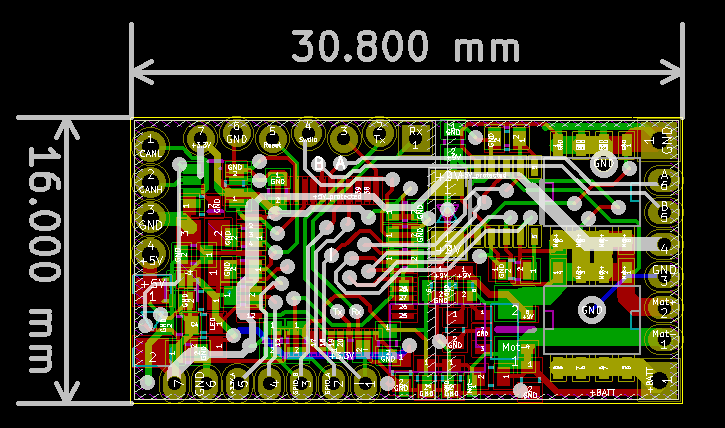
Motor board
On the following figure you can see the layout of the motor board we designed. It is a dense, 4 layer PCB with the following features:
- STM32F303 ARM processor
- CAN interface
- Can drive DC motors up to XX watts
- Can be retrofitted in RC servomotors to have cheap "smart servos"
This board is Open Hardware licensed under a Creative Commons license. You can find all the details about it in the Github repository